| Specifications |
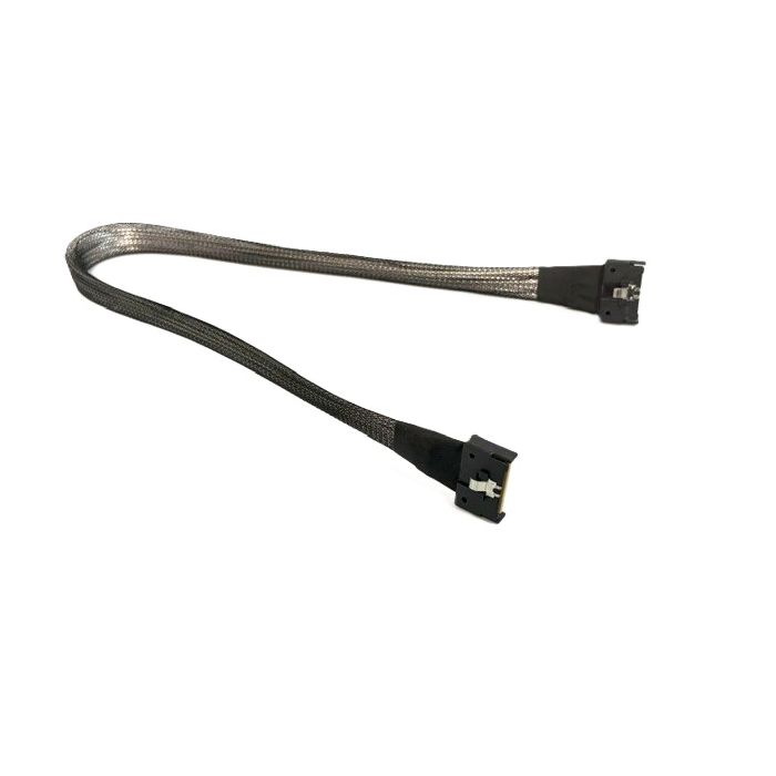
This is an internal, shielded high-speed cable assembly built to the SFF-TA-1016 (MCIO – Mini Cool Edge IO) specification, using the 74-position connector variant on both ends. It's the standard interconnect used inside servers and storage systems to carry PCIe, SAS, or Ethernet-class signals between a host (CPU/HBA/RAID controller) and a backplane, drive bay, or riser card.
Connector / Pinout Configuration
- Contact count: 74 pins per connector, arranged in two rows (commonly labeled A and B), each with 37 positions.
- A1-to-A1, B1-to-B1 mapping means this is a straight-through (non-crossover) pinout — pin A1 on connector 1 connects directly to pin A1 on connector 2, and B1 to B1, and so on through the full 74 positions. This is the standard configuration for connecting a host port to a backplane/expander port where the backplane or device performs its own lane re-ordering — as opposed to a "crossover" cable (A1-to-B1 style) used in direct host-to-host or certain re-timer applications.
- Signal groups per SFF-TA-1016:
- High-speed differential pairs (Tx/Rx) for up to x8 lanes in the 74-pin form factor (expandable to x12 without sidebands, per the SNIA spec)
- Ground pins interspersed for shielding/isolation between differential pairs
- Sideband/low-speed pins (presence detect, reset, clock, management/I2C, power-good, etc.)
- Impedance: Differential pairs are typically controlled to 85 Ω for signal integrity at high data rates.
- Length: 500 mm (≈19.7 in), a common mid-length option balancing routing flexibility with signal loss.
10 Best Characteristics
- High bandwidth support — Handles PCIe Gen3/Gen4/Gen5 (and often Gen6-ready), supporting up to 32 GT/s per lane (NRZ) and 56–64 GT/s PAM4 signaling.
- Multi-protocol flexibility — Same physical cable/connector supports PCIe, SAS 3.0/4.0, and 25G+ Ethernet, reducing the need for protocol-specific cabling.
- x8 lane density in a compact footprint — 74-pin form factor delivers a full x8 high-speed lane count (or x12 without sidebands) in a much smaller connector than legacy Mini-SAS HD.
- 85-ohm controlled impedance — Twinax/shielded internal construction minimizes crosstalk and signal loss, critical for Gen5-class signaling.
- Straight (A1–A1, B1–B1) pin mapping — Preserves lane order end-to-end, simplifying host-to-backplane wiring and avoiding the need for lane re-mapping in firmware/BIOS.
- 500mm length for flexible routing — Long enough to reach across most server chassis and rack layouts while limiting insertion loss compared to 1m+ variants.
- Robust mechanical design — SFF-TA-1016 connectors use a 0.6mm pitch with strong retention/latching and rated wrenching strength (~25N), suited to repeated service in data center environments.
- Improved airflow/thermal design — Thin, round or ribbon-style cable jacketing (depending on vendor) reduces bulk versus older cable types, aiding chassis airflow.
- Backward/forward compatibility — Works across PCIe generations (3/4/5) and is positioned as forward-compatible with future PCIe 6.0 deployments.
- Standardized, multi-vendor interoperability — Because it follows the open SNIA SFF-TA-1016 spec, cables and connectors from different manufacturers (Amphenol, TE, Molex, etc.) are broadly interoperable, easing sourcing and replacement.
|